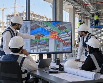
Construction sites can quickly become arenas for costly on-site disputes when MEP installation teams begin their work and discover that actual site conditions differ significantly from what was shown in separate design drawings.
Large HVAC ducts intersect with downstand concrete beams, cable-tray routes clash with fire-protection pipes, and the space required for maintenance access above suspended ceilings disappears.
This confusion is not merely an administrative issue. It directly drains project budgets through variation orders caused by rework, breaking concrete after it has been cast, and compromising structural safety. The rigorous implementation of MEP drawing coordination before any procurement or fabrication begins is the essential engineering measure required to move a project from improvised on-site solutions to controlled execution.
Direct Answer
MEP drawing coordination is based on coordinating HVAC, drainage, water-supply, fire-protection, and electrical cable routes with architectural and structural drawings in a unified model before construction. This process ensures that all hard and soft clashes are resolved in advance, structural sleeves and openings are accurately positioned within concrete elements, and building services are routed according to an established hierarchy and the requirements of the Saudi Building Code, preventing demolition work and programme delays.
Executive Summary for Project Managers and Coordination Teams
- Early coordination prevents more than 85% of on-site clashes that would otherwise reduce profit margins and increase specialist contracting costs.
- Successful engineering coordination requires applying the “gravity and rigidity priority rule,” which gives priority to gravity drainage and major ventilation systems over flexible routes such as electrical cables.
- Approval of Structural Opening Drawings is essential before casting slabs and retaining walls to protect reinforcement from drilling and demolition work.
- Partnering with an integrated general contractor that combines civil, MEP, and metal fabrication works helps eliminate complex interfaces and establishes unified execution references.
1. What Is MEP Drawing Coordination, and Why Are Design Drawings Alone Insufficient?
MEP drawing coordination, or Mechanical, Electrical, and Plumbing Coordination, is an advanced engineering stage that transforms preliminary designs into coordinated and constructible Composite Services Drawings.
Contractual design drawings are not intended to specify the precise route of every service down to the millimetre. They generally illustrate the engineering concept, load distribution, start and end points, and operating capacities.
Problems arise when contractors develop their work independently from one another. The HVAC contractor prepares drawings without coordinating with the electrical contractor, while the plumbing contractor installs piping without consulting the structural steel designer.
This separation leads to hard clashes, such as a pipe intersecting with a concrete element, and soft clashes, such as high-voltage cables passing too close to hot-water pipes in violation of code and approved insulation requirements.
2. Routing Priority Within Architectural Spaces
Spatial conflicts between services should not be left to the judgement of site technicians. They must be resolved through an engineering protocol that determines routing priority according to physical constraints and the cost of modification.
- Gravity drainage systems: Sanitary and stormwater drainage pipes have the highest priority because they depend on fixed gradients that cannot be interrupted or altered without creating serious blockage risks.
- Major HVAC ducts: These have the second-highest priority because of their large cross-sections, their need for relatively straight routes to reduce pressure losses and fan-energy consumption, and the difficulty of rerouting them around other systems.
- Pressurised pipes and major services: These include chilled-water lines, principal fire-protection pipes, and domestic water-supply networks. They offer greater flexibility through the use of bends but require thick insulation and approved supports capable of carrying substantial loads.
- Cable trays and low-current routes: These systems are more flexible and can be redirected around structural and mechanical obstacles, provided that the approved bending radius of power cables is maintained.
3. Integrating MEP Works with Concrete and Steel Structures
Effective MEP drawing coordination requires strong interfaces with structural and architectural disciplines to protect the facility through the following measures.
A. Structural Openings and Builders’ Work Drawings
All service penetrations through concrete beams, retaining walls, and floors must be converted into approved detailed drawings before reinforcement and concrete casting begin:
- Install steel or plastic sleeves with watertight puddle flanges in tanks and basements.
- Coordinate with the structural engineer to avoid creating openings in high-shear zones near columns or in areas containing primary reinforcement.
- Obtain approval for duct openings through steel structures to ensure that the load-bearing capacity of beams and trusses is not compromised.
B. Maintenance Access and Available Architectural Space
Coordination must ensure that operations teams can access critical components easily:
- Maintain vertical and horizontal clearances of at least 100–150 mm around pipes and ducts for installing and inspecting thermal insulation.
- Align control valves, pressure-balancing valves, and fire-damper actuators with access panels in suspended ceilings.
- Preserve the required clear ceiling height in corridors and offices in accordance with the approved architectural drawings.
4. Matrix for Resolving Common Engineering Clashes
The following table presents the approved method for resolving common conflicts between different building systems:
| On-Site Clash |
Conflicting Disciplines |
Approved Coordination Solution |
Preventive Action and Mandatory Requirement |
| Air duct intersecting with a sloped drainage pipe |
HVAC and plumbing |
Reroute the duct or divide its cross-section while maintaining the required total area |
Never change the drainage-pipe gradient, as this would affect gravity flow |
| Cable tray clashing with a fire-protection pipe |
Electrical and fire protection |
Lower the cable tray so that it passes beneath the fire-protection pipe |
Maintain at least 150 mm of separation to protect against moisture leakage |
| Chilled-water line intersecting with a downstand concrete beam |
Mechanical and structural |
Assess whether the pipe can pass below the beam while adjusting the suspended-ceiling arrangement |
Drilling through downstand beams is prohibited without written approval from the structural consultant |
| Power cables overlapping with low-current cables |
Power and data/ELV |
Use completely separate cable trays and routes |
Maintain at least 300 mm of separation to prevent electromagnetic interference |
| HVAC duct crossing an expansion joint |
Mechanical and architectural/structural |
Install a fire-resistant flexible canvas connection |
Install an approved fire and smoke damper where the duct penetrates a fire-rated wall |
5. Compliance with the Saudi Building Code and Safety Requirements
No MEP drawing coordination study in Saudi Arabia can be considered complete unless it complies fully with the applicable regulatory requirements:
- Saudi Fire Code (SBC 801): Fire and smoke dampers must be installed wherever air ducts penetrate fire-rated walls or floors. Approved UL-listed firestopping systems must be used to seal spaces around cables and pipes.
- Saudi energy conservation and insulation codes (SBC 601/602): Thermal insulation thicknesses for HVAC ducts and chilled-water pipes must be verified to prevent condensation, structural corrosion, and energy loss within enclosed spaces.
- Saudi Electrical and Plumbing Codes (SBC 401/SBC 501): Permissible voltage-drop limits, cable-tray and trunking fill ratios, and reliable grounding of all equipment and suspended steel service routes must be considered.
6. Verification and Approval: From Modelling to the Site
Coordination governance requires a rigorous review process to ensure that paper or digital drawings are converted into conflict-free on-site work through the following stages:
- Automated clash detection: Generate clash-detection reports between three-dimensional models using advanced coordination software. Clashes should be classified by priority, with zero-tolerance and critical conflicts resolved first.
- Issuing Composite Services Drawings: Engineers from all relevant disciplines—including civil, architectural, mechanical, and electrical—must sign the combined drawing to confirm agreement on elevations and coordinates.
- Installing multi-service supports: Design shared trapeze supports instead of installing individual, uncoordinated hangers in concrete slabs. This reduces concentrated loads and creates a more organised technical space.
7. General Contracting and MEP Integration Solutions with MEPCO
Resolving complex engineering clashes on major projects requires a principal contractor with a comprehensive perspective that goes beyond dividing the work among multiple disconnected companies. This is where MEPCO’s experience and capabilities provide significant value.
Through MEPCO’s integrated General Contracting services, clients receive centralised management that combines civil and structural disciplines with advanced MEP networks under one engineering leadership team. This ensures that coordinated construction drawings are properly controlled before on-site work begins.
MEPCO also offers advanced manufacturing capabilities through its Industrial and Metal Fabrication division, enabling steel structures, heavy-duty service supports, and mechanical frames to be manufactured accurately according to approved coordination drawings.
This integration of execution and manufacturing eliminates communication gaps between structural, mechanical, and electrical teams. It creates a controlled and efficient working environment that protects projects against delay penalties and reduces future operations and maintenance costs.
8. Engineering Coordination Checklist Before Installation
Before installing pipework or suspending air ducts on-site, confirm that the following coordination requirements have been satisfied:
9. Conclusion and Call to Action
Early investment in MEP drawing coordination is not merely an additional design-office stage. It is a technical safeguard that protects budgets, prevents contractual disputes, and supports the delivery of highly reliable engineering projects.
Accurate spatial routing and the resolution of clashes within digital models save both the owner and contractor from costly concrete demolition and ensure that the completed facility is safe and easy to operate in accordance with Saudi Arabia’s approved architectural and structural standards.
If you are preparing shop drawings for your project or require an integrated contracting partner capable of managing, coordinating, and executing complex structural and MEP works, contact MEPCO’s engineering team to discuss your project’s technical requirements and explore integrated solutions that support the success and sustainability of your investment.
Frequently Asked Questions About MEP Drawing Coordination
Q1: What is the main difference between Composite Services Drawings and Structural Opening Drawings?
Composite Services Drawings combine all MEP service routes within a single coordinated drawing to resolve spatial clashes and determine installation elevations.
Structural Opening Drawings identify the positions, dimensions, and technical requirements of the openings and sleeves needed in concrete and steel elements so that services can pass through them before concrete casting begins.
Q2: What are the risks of creating openings for ducts and pipes in concrete beams after casting?
Unplanned core drilling after casting may cut through primary reinforcement or critical shear reinforcement. This can reduce the structural capacity of the building and cause serious cracking or partial structural failure.
It may also invalidate structural warranties and lead inspection authorities to reject the building.
Q3: How does the Saudi Building Code affect MEP drawing coordination priorities?
The Saudi Building Code imposes strict technical requirements on service routes. These include separating power and low-current systems in accordance with SBC 401, installing fire and smoke dampers under SBC 801, and applying thermal insulation requirements to air ducts and chilled-water pipes under SBC 601/602 to prevent condensation and structural corrosion.
Q4: When should MEP drawing coordination begin?
Coordination should begin immediately after the preliminary architectural and structural designs have been approved and during the preparation of shop drawings.
It must be completed before concrete casting or the procurement of long-lead materials begins. This ensures that sleeves and openings are incorporated into the structural drawings in advance and prevents subsequent clashes.
Q5: Why is appointing an integrated contractor an effective way to prevent MEP clashes?
An integrated contractor manages structural, mechanical, electrical, and metal fabrication disciplines under one technical framework.
This arrangement eliminates the traditional on-site disputes between separate contractors and establishes a single engineering authority responsible for drawing coordination, execution quality, and adherence to the project programme.



 MEPCO