
MEPCO is one of the leading construction and contracting companies in Saudi Arabia. Established in 1420 AH, the company has been steadily progressing to keep pace with the rapid urban development witnessed in the Kingdom.
MEPCO is one of the leading construction and contracting companies in Saudi Arabia. Established in 1420 AH, the company has been steadily progressing to keep pace with the rapid urban development witnessed in the Kingdom.


 MEPCO
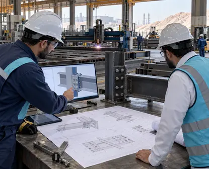
Transforming structural designs into actual production instructions is one of the most critical stages in steel structure and industrial building projects. Once steel has been formed, cut, drilled, and welded in the factory, making simple modifications on-site is no longer practical.
Discovering a discrepancy of only a few millimetres in anchor bolt holes—or an incorrect angle where a beam plate meets a concrete support—during lifting and erection can bring site operations to an immediate standstill. It may leave heavy cranes idle, lead to costly refabrication, and introduce structural risks if unauthorised field modifications or hole enlargement are used as temporary remedies.
The fundamental engineering solution lies in the rigorous review and comprehensive approval of steel structure shop drawings before cutting and welding equipment is authorised to begin production. The greater the accuracy of the steel structure shop drawings, the lower the risk of coordination conflicts, refabrication, and erection delays.
Prepared for consulting engineers, structural designers, and steel contractors in Saudi Arabia, this guide explains the critical documents and technical requirements that must be reviewed and approved to achieve fabrication in accordance with leading structural and regulatory standards.
Direct Answer
Approving steel structure shop drawings requires a coordinated comparison between contractual design drawings and detailed shop and erection drawings. The review must verify steel grades and thicknesses, confirm that moment and shear connections can withstand the specified wind and seismic forces, check anchor bolt coordinates and elevations, approve welding symbols in accordance with AWS D1.1, and confirm compliance with hot-dip galvanizing and fire-resistant coating requirements under the Saudi Building Code before fabrication begins.
Some non-specialist project managers assume that the approval of contractual design drawings authorises the factory to begin steel fabrication. This assumption represents a serious engineering risk.
Design drawings prepared by the structural engineer generally indicate grid lines, principal structural member sections, such as columns and beams, and maximum design forces, including moments, shear forces, and axial loads. They do not provide the detailed mechanical information required to manufacture every individual component.
This is the purpose of steel structure shop drawings, also known as shop or fabrication drawings. The steel detailer divides the building into thousands of separate components and plates, assigns each item a unique mark number, and specifies its exact dimensions, hole locations, cutting and bevel angles, and weld types and sizes.
If the consultant does not review the steel structure shop drawings against the original structural design philosophy, an incorrect assumption made by the fabricator may become a defective component that is difficult to erect or potentially compromises the building’s stability.
A systematic review matrix should be used when checking steel structure shop drawings to ensure that no element affecting fabrication accuracy or erection safety is overlooked.
| Review Item | Engineering Verification Requirements | Applicable Reference | Approval Requirement |
|---|---|---|---|
| Steel grades and material specifications | Verify that section and plate grades, such as ASTM A36 or S355JR, match the approved specifications | SBC 306 and SASO specifications | Mechanical and chemical properties must match the Material Test Certificates |
| Anchor Bolt Plan | Verify bolt grids, diameters, embedment lengths, and projections above concrete | Concrete foundation drawings and ACI requirements | Coordinates must match the field survey, with temporary setting templates provided |
| Moment and shear connection design | Review connection plate thicknesses and high-strength bolt diameters | AISC 360 | Detailed calculations must demonstrate adequate connection capacity |
| Welding symbols and details | Review weld type, effective throat thickness, and welding-consumable classification | AWS D1.1 | Details must comply with the fabricator’s approved WPS |
| Galvanizing and treatment openings | Verify vent and drain holes in hollow sections | ASTM A123 and ISO 1461 | Openings must be structurally safe and positioned without compromising appearance |
| Assembly and erection drawings | Review erection sequence and temporary bracing locations and types | Construction management and occupational safety requirements | Part marks must be clear, with sufficient space for tightening and erection equipment |
Connections require particular attention during the review of steel structure shop drawings because many steel structure failures originate at connection points rather than through the fracture of primary members.
The engineering review should cover the following:
The Anchor Bolt Plan is the principal interface document between the civil and concrete contractor and the structural steel fabricator. For this reason, steel structure shop drawings must contain all details required to prevent conflicts between completed foundations and column base plates.
Steel columns should not be cut or assembled before completing the following checks:
Saudi Arabia’s environmental conditions make surface-treatment requirements an essential part of fabrication detailing. Therefore, steel structure shop drawings must clearly define corrosion-protection and fireproofing requirements before production begins.
The review should cover:
The engineering value of approved steel structure shop drawings is fully realised only when the review covers potential clashes between the steel frame and HVAC, electrical, plumbing, and fire-protection systems.
Commercial and industrial buildings may require ductwork or main fire-protection pipes to pass through steel beams to preserve the required clear height.
The drawings must identify the position and size of every opening and provide the required reinforcement details approved by the structural consultant. No thermal cutting or unapproved field opening should be permitted after the steel member leaves the factory.
Cable tray supports, ductwork, pipework, and overhead cranes must be reviewed. Secondary connection plates and support brackets should be incorporated into the fabrication drawings.
This prevents uncontrolled field welding on primary load-bearing members and reduces the risk of unintended stresses or deformations.
Major industrial and engineering projects require a fabricator with the technical and digital capabilities needed to transform structural designs into fully coordinated fabrication models.
Through MEPCO Metal Industries, MEPCO uses advanced three-dimensional modelling and BIM technologies to produce and review steel structure shop drawings with the accuracy required by laser-cutting lines and CNC forming equipment.
These capabilities are integrated with MEPCO’s General Contracting services, providing owners and consultants with unified coordination between structural steel drawings, MEP service routes, and foundation works.
This integrated approach supports the early verification of anchor bolts, connections, and protective treatments. It also reduces disputes and variation orders while accelerating the fabrication, delivery, and erection of steel structures throughout Saudi Arabia.
Before issuing Code A approval for steel structure shop drawings, the consultant should confirm that the following requirements have been met:
Investing in the review and verification of steel structure shop drawings is an essential engineering safeguard for completing a project within its approved budget and programme.
Early and accurate approval transforms fabrication into a fast, controlled, and high-quality process. It reduces disputes and field modifications and supports the long-term safety and durability of steel structures in accordance with applicable Saudi codes and regulations.
If you are preparing steel structure shop drawings or planning the fabrication of a steel building or industrial structure, contact the engineering team at MEPCO Metal Industries to discuss your project and obtain specialist engineering support for accurate and efficient execution.
Shop drawings focus on each individual component and provide factory personnel and machinery with the cutting dimensions, holes, and welding details required for every plate, beam, or column.
Erection drawings provide the overall site assembly information required to install and connect the numbered components to one another and to the concrete foundations.
Using gas flames or thermal cutting to enlarge bolt holes without formal engineering approval may alter the steel’s microstructure and affect its resistance to shear and tension. It can also compromise proper bolt contact and connection behaviour.
Such modifications may invalidate the fabricator’s warranties and expose the connection to failure under live, wind, or seismic loads.
SBC 306 requires structural welding to comply with AWS D1.1. Welding Procedure Specifications and Procedure Qualification Records must be submitted, together with valid welder qualifications.
The required extent of non-destructive testing must also be identified for critical connections, including ultrasonic and magnetic-particle testing where applicable.
Vent and drain holes are mandatory when sealed hollow sections are to be hot-dip galvanized.
They prevent trapped air from expanding under the temperature of the molten zinc bath and allow zinc to enter and drain from the section, protecting internal surfaces against corrosion.
The steel contractor, fabricator, and appointed steel detailer remain directly responsible for dimensional accuracy, part identification, and fabrication details.